Number Systems
Author : Anjali Singh, Digital Design Engineer, SignOff Semiconductors
To start with VLSI skill development, we need to enhance our frontend skills. check the ASIC flow at ASICvsFPGA, which describes the frontend and backend flow for the full chip development. Frontend starts with specification gathering and architecture designing from the specifications gathered. To develop the architecture design, we need to have a good command over digital design. Digital design consists of logic gates, combinational circuits and sequential circuits. These all together makes the hardware and to interact with hardware we need a common language which can be understood by both user and machine. This brings the need of a number system which involves the representation of the numbers in different formats which is explained below.
Number Systems
In digital electronics, the number system is used to represent information. We all are familiar with the number system in which an ordered set of ten symbols (0,1,….,9) known as digits are used to specify any number. This number system is known as the decimal number system. The radix or base of this number system is 10 (number of distinct digits). A collection of these digits makes a number which in general has two parts : integer part (digits before the radix point) and fractional part (after the radix point) separated by a radix point (.)
(N)b=dn-1,dn-2,…….,d1,d0 . d-1,d-2,……,d-m
N= a number, b= radix or base of the number system, n= number of digits in the integer part, m= number of digits in the fractional part, dn-1= most significant bit, d-m =least significant bit.
The digits in a number are placed side by side and each position in the number is assigned a weight. Some of the common number systems are listed in Table1 and these number systems are widely used in digital systems like microprocessors, logic circuits, computers, etc.
Table 1:
| Number System | Radix | Symbols |
|---|---|---|
| Binary | 2 | 0 and 1 |
| Decimal | 10 | 0,1,2,3,4,5,6,7,8,9 |
| Octal | 8 | 0,1,2,3,4,5,6,7 |
| Hexadecimal | 16 | 0,1,2,3,4,5,6,7,8,9,A,B,C,D,E,F |
Conversion from one Number System to Another:
-> Steps to convert Decimal number to other number system(Table2):
- Divide the given number by the radix of the new number system. Example : (15)10 to (?)2. Table3.
- The remainder from step1 is stored as LSB.
- Step1 and 2 are repeated until quotient becomes zero. The last remainder recorded becomes the MSB.
Table 2:
| Steps | Operation | Result | Remainder |
|---|---|---|---|
| 1 | N/r | q1 | rem1 (LSB) |
| 2 | q1/r | q2 | rem2 |
| 3 | … | … | … |
| 4 | qn/r | 0 | rem_n (MSB) |
NOTE :
N : Given number.
r : radix of the new number system i.e 2 or 8 or 16.
q : quotient obtained on successive division.
rem : remainder recorded.
Table 3:
| Steps | Operation | Result | Remainder |
|---|---|---|---|
| 1 | 15/2 | 7 | 1 |
| 2 | 7/2 | 3 | 1 |
| 3 | 3/2 | 1 | 1 |
| 4 | 1/2 | 0 | 1 |
->Steps to convert other number to Decimal number system(Table4):
- Determine the position of each digit. Example (101)2 to (?)10.Table5.
- Multiply each digit with radix(positional weight).
- Sum the products calculated in step2.
Table 4:
| Steps | Given Number | Decimal Number |
|---|---|---|
| 1 | wxyz | ((W * r3) + (X * r2) + (Y * r1)+ (Z * r0)) |
| 2 | wxyz | (s1 + s2 + s3 + s4) |
| 3 | wxyz | SUM |
NOTE :
WXYZ : given number.
r : radix of the given number.
s1,s2… : individual sums.
Sum : final sum i.e, the decimal equivalent number.
Table 5:
| Steps | Given Number | Decimal Number |
|---|---|---|
| 1 | 101.1 | ((1 * 22)+( 0 * 21)+(1 * 20)+(1 * 2-1)) |
| 2 | 101.1 | (1+0+4+0.5) |
| 3 | 101.1 | 5.5 |
Questions to try :
- (135)y + (144)y =(323)y . Find the radix (y).
- (123)5=(x8)y . Find x and y [Hint : always ensure that radix > individual digits in that radix number system]
Complements:
Complements are used in the digital computers in order to simplify the subtraction operation and for the logical manipulations. For each radix system there are two types of complements.
- Radix complement. [r’s complement]
- Diminished radix complement. [(r-1)’s complement]
(r – 1)’s Complement :
Given a number N in base ‘r’ having ‘n’ digits, the (r-1)’s complement of N is defined as
[(rn – 1) – N ].
Example for r=10, and r-1=9, so the 9’s complement is
-> [(10n – 1) – N]
-> [(104 – 1) – N]
-> [(10000 – 1) – N]
-> 9999 -N.
Thus 9’s complement is obtained by subtracting 9 from each digit of given number N.
I.e, N=4567. Then 9’s complement is [9999 – 4567]=5432.
Similarly the (r-1)’s complement of binary ,octal or hexadecimal numbers are obtained by subtracting each digit by 1 ,7 or ‘F’ respectively.
( r )’s Complement :
The r’s complement for a given number N in a base ‘r’ having ‘n’ digits is defined as [rn – N].
Thus it’s observed that r’s complement is obtained by adding 1 to (r-1)’s complement.
Example for r=10, the 10’s complement of 4567 is [(r -1)’s complement + 1] = [5432 + 1]=5433.
Steps to find r’s complement without finding (r-1)’s complement.
- Leave all least significant 0s unchanged.
- Subtract the 1st non-zero LSB by ‘r’ .
- Subtract all higher significant bits with (r-1).
Example :find 8’s complement of (56700)8
- 56700 (keep the last two zeroes unchanged)
- 77800 – 56700 =21100 ( Subtract the 1st non-zero LSB from ‘8’ & Subtract all higher significant bits from 7.)
8’s complement of (56700)8 is 21100.
Signed-magnitude representation:
n this representation an extra MSB is used to represent the sign of the binary number. And it does not hold any weight. If MSB is ‘1’ then the number is called a negative number, otherwise it’s called a positive number.
Range: -((2n-1)-1) to ((2n-1)-1)
Advantage:
- Only MSB is tested to know the sign of the number.
Disadvantage:
- Using 4 bits we can have 24 i.e, 16 patterns. In unsigned representation, we were able to represent 16 numbers: 0, 1, 2, 3, 4, 5, 6, 7, 8, 9, 10, 11, 12, 13, 14, and 15. But with signed magnitude, we are only able to represent numbers: -7, -6, -5, -4, -3, -2, -1, 0, 1, 2, 3, 4, 5, 6, and 7.
- Addition of any -ve number with a non-negative number is simple, the issue is seen while adding 2 numbers with the same sign.
Example :
(5)10 + (7)10=(12)10
0101
+ 0111
1100 i.e (1100)2=(-4)10
As seen in above example the result (-4) is not as expected, thus whenever an overflow bit is expected then the sign bit of the given number is extended before performing the operation and this technique is known as sign extension.To extend the sign bit, add bits on the left, duplicating the most significant bit. This preserves the sign of the number and does not alter its value as shown below.
00101
+ 00111
01100 i.e (01100)2=(+12)10 expected result.
Thus addition of numbers represented using signed magnitude method is tedious.
Signed Bit representation using 1’s complement:
In a binary number, if each 1 is replaced by 0 and each 0 by 1 then the result is known as 1’s complement of the given number. Example ,(0101)2 represents (+5)10, whereas (1010)2 represents (-5)10 in this representation. Even here MSB is ‘0’ for +ve number and ‘1’ for -ve number.
Range : -((2n-1)-1) to ((2n-1)-1)
Advantage:
- Simple to represent the signed numbers.
- Simpler Add/Subtract circuit design (subtracting a number from another involves complementing the subtracted and then adding it to the other number).
Example :
(5)10 + (-2)10=3
(-2)10=(1101)2
0101
+ 1101
0010
+ 1
0011
Disadvantage:
- One’s complement has a “positive” zero and a “negative” zero.
- Though addition/subtraction is simple, we have to keep track of overflow bit. If an overflow has occurred, a further addition of a 1 is necessary
Table6 :
Signed 1’s complement.
| -7421 code | Decimal equivalent no. |
|---|---|
| 0000 | 0 |
| 0001 | 1 |
| 0010 | 2 |
| 0011 | 3 |
| 0100 | 4 |
| 0101 | 5 |
| 0110 | 6 |
| 0111 | 7 |
| 1000 | -7 |
| 1001 | -6 |
| 1010 | -5 |
| 1011 | -4 |
| 1100 | -3 |
| 1101 | -2 |
| 1110 | -1 |
| 1111 | 0 |
Signed Bit representation using 2’s complement:
The primary advantage of two’s complement over one’s complement is that two’s complement only has one value for zero.
Next, to add numbers using one’s complement you have to first do binary addition, then add in an end-around carry value.
Two’s complement has only one value for zero, and doesn’t require carry values.
Range : -((2n-1)) to ((2n-1)-1) 2’s complement.
Table6 :
Signed 2’s complement.
| -8421 code | Decimal equivalent no. |
|---|---|
| 0000 | 0 |
| 0001 | 1 |
| 0010 | 2 |
| 0011 | 3 |
| 0100 | 4 |
| 0101 | 5 |
| 0110 | 6 |
| 0111 | 7 |
| 1000 | -7 |
| 1001 | -6 |
| 1010 | -5 |
| 1011 | -4 |
| 1100 | -3 |
| 1101 | -2 |
| 1110 | -1 |
| 1111 | 0 |
Example : 8-bit representation of -9 in signed magnitude, 1’s complement and in 2’s complement.
(9)10=(00001001)2
MSB=’1’ for a negative number.
LSB =’0’ for a positive number.
1’s complement representation:
1’s complement of 9= 11110110
| -ve(sign) | -ve | -ve | -(24 -1) | 23 | 22 | 21 | 20 |
| 1 | 1 | 1 | 1 | 0 | 1 | 1 | 0 |
Signed magnitude representation:
| -ve(sign) | 26 | 25 | 24 | 23 | 22 | 21 | 20 |
| 1 | 0 | 0 | 0 | 1 | 0 | 0 | 1 |
2’s complement representation:
| -ve(sign) | -ve | -ve | -24 | 23 | 22 | 21 | 20 |
| 1 | 1 | 1 | 1 | 0 | 1 | 1 | 1 |
Note : Extension of sign bit will not change the decimal equivalent value.
Digital codes:
The group of symbols are called code. The digital data is represented, stored and transmitted as a group of bits. This group of bits are also called binary code.
Binary codes can be classified into two types.
- Weighted codes [example :binary and BCD codes].
- Non Weighted codes [example : Excess-3 and gray.]
If the code has positional weights, then it is said to be a weighted code. Otherwise, it is an Non weighted code. Weighted codes can be further classified as positively weighted codes and negatively weighted codes.
BCD code [Binary coded decimal]:
Table 8:
| Decimal Number | BCD code | Excess-3 |
|---|---|---|
| 0 | 0000 | 0011 |
| 1 | 0001 | 0100 |
| 2 | 0010 | 0101 |
| 3 | 0011 | 0110 |
| 4 | 0100 | 0111 |
| 5 | 0101 | 1000 |
| 6 | 0110 | 1001 |
| 7 | 0111 | 1010 |
| 8 | 1000 | 1011 |
| 9 | 1001 | 1100 |
We have 10 digits in the decimal number system. To represent these 10 digits in binary, we require a minimum of 4 bits. But, with 4 bits there will be 16 unique combinations of zeros and ones. Since, we have only 10 decimal digits, the other 6 combinations of zeros and ones are not required.
Excess-3 code:
- This code doesn’t follow positional weight principle thus termed as non-weighted code.
- We will get the Excess 3 code of a decimal number by adding three 0011 to the binary equivalent of that decimal number. Hence, it is called Excess 3 code (ref table8).
- It is a self-complementing code.
Example :
Given number: (786)10
This number has 3 decimal digits 7, 8 and 6. From table8, we can write the Excess 3 codes of 7, 8 and 6 are 1010, 1011 and 1001 respectively.
Therefore, the Excess 3 equivalent of the decimal number 786 is 101010111001.
Gray code:
It is a very useful code in which a decimal number is represented in binary form in such a way that each gray-code number from the preceding and the succeeding number differs by a single digit only. Example gray code for decimal number 5 and 6 is 0111 and 0101 respectively where only the last 2nd bit has changed. This code is popularly used in shaft encoder which represents the angular position of the shaft.
Binary code to Gray Code Conversion
Follow these steps for converting a binary code into its equivalent Gray code.
- Retain the MSB of binary code.i.e this bit becomes MSB of the gray code.
- Perform xor operation between the MSB bit and the next bit and the result become the next bit of gray code.
- Repeat the above step till the LSB of binary code is reached.
Example :
Given, binary code is B2B1B0
Step 1 − g2=B2
Step 2 − g1=B2 xor B1
Step 3 − g0=B1 xor B0
(1000)2 =(1100)gray_code.
Gray code to Binary Code Conversion
Let the given gray code be G0G1G2 and the binary equivalent code be B2B1B0.
Therefore,
B2=G2
B1=B2 xor G1
B0=B1 xor G0
Alphanumeric codes :
Many times digital systems need to handle data that may consist of numbers, letters, and special symbols. Therefore it is important to have binary code for alphabets too. In general two alphanumeric codes are used :
- Extended BCD Interchange Code (EBCDIC).
- American Standard Code for Information Exchange (ASCII).
Error Detecting and Correcting Codes:
Data can be corrupted in transmission or storage by a variety of undesirable phenomenon, such as radio interference, electrical noise, power surges, bad spots on disks or tapes, or scratches or dirt on CD or DVD media. It is useful to have a way to detect (and sometimes correct) such data corruption.
In order to correct such codes two types of code are used :
- Error detecting code(odd and even parity codes).
- Error correcting code (Hamming code).
Parity codes:
To detect error in a code parity check is done followed by other steps(like checksum and cyclic redundancy check). Parity check is done by adding an extra bit, called parity bit to the data to make number of 1s either even in case of even parity, or odd in case of odd parity.
- In case of even parity: If the number of 1s in a given data word is even then parity bit value is 0. If the number of 1s is odd then parity bit value is 1.
- In case of odd parity: If the number of 1s in a given data word is odd then parity bit value is 0. If the number of 1s is even then parity bit value is 1.
The above explained is a single data word parity check. Think of a transmission channel where you have to send multiple data words. Here in this case, you have to check the parity for each data word in row and column wise and send a seperate data word which consists of only parity bits of the corresponding original data words that are being transmitted. Check below example for the detailed understanding.
Example:
Data word to be sent : 100110 001100 111000 101010
Here d1 = 100110, d2 = 001100, d3 = 111000, d4 = 101010 and we have to use even parity.
Even Parity checking for the d1,d2,d3,d4:
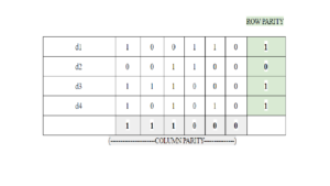
Here you got row parity and column parity, which should be sent along with data words to the receiver, so that the receiver will do the parity checking based on this parity data words that have been sent. So finally the data word that should be sent at transmitting side should be :
| 111000 | 001011 | 101010 | 111000 | 001100 | 100110 |
| C.P | R.P | d4 | d3 | d2 | d1 |
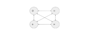
Hamming code:
It is an error-correction code that can be used to detect and correct the errors that can occur when the data is moved or stored from the sender to the receiver. It is a technique developed by R.W. Hamming for error correction.
Basic Units of Information :
- Bit: The smallest unit of data on a binary computer or a digital system is a single bit. Bit is an abbreviation for Binary digit. Individual bit is usually difficult to manipulate thus other data types are used to represent boolean values.
- Nibble: 4 bits.
- Byte: 8 bits.
- Word: The standard memory bus width in an architecture .(example 16-bit, 32-bit, 64-bit words).
Comments are closed.