FinFET-2 (Multi-Gate FinFET)
Author : Sarvesh Singh, Physical Design Engineer, SignOff Semiconductors
In 1965, Gorden Moore in his paper predicted that how number of transistors in integrated circuit get double in every 18 month. Even though in 1990, a new type of substrate named SOI (Silicon-on-insulator) was introduced which improved the speed and power consumption, the first integrated circuit transistor was fabricated on “Bulk” silicon wafers.
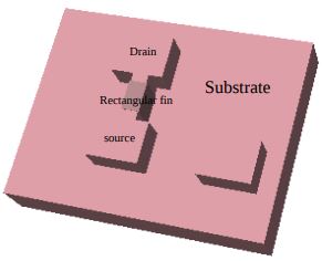
Figure 1: Single fin rectangular Finfet
Some parameters in FinFET:
1. Current:- In multi-gate FET, the total current is almost equal to the sum of all currents flowing under the gate electrode [carriers have same mobilty under all the gates]. As we increase the number of gate the current get multiplied by the value of current in single gate FET (keeping all the gate dimension same).
Current in multigate FET= (Number of gate)* (current in single gate FET)
We can say that current in double-gate FET is double that of the single gate FET of equal gate length and width. As we increase the number of gates, it will increase the current but it has limitations, i.e difficult to fabricate, corner effects etc. For example, triangular fin will have double gate, square fin will have a triple-gate and pentagonal fin will have quad-gate around it. Instead of increasing the No. of gates, we go for multi-fins of simple shapes (i.e rectangular, square). We can get the large current if we increase the fins in a device.
By increasing fins we will get lot of advantages:
- large current.
- Area of device get reduce.
- fabrication is little bit easy.
Current in multi-fin FET= No. Of fins* current in single fin of device
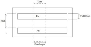
Figure 2: (a) Top view
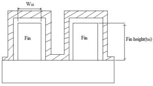
Figure 2: (b) sideview of FinFET
Note:
Increasing fin height also increases the current but it is little bit difficult to fabricate high height fin devices so we use multi-fin of small height.
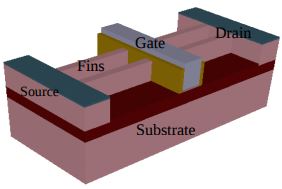
Figure 3: 2-Fin FinFET
2. Corner Effects:-As we discussed that there is a limitation on fin shapes, here corner effect comes into the picture. Corner effects on the fin lead to the premature channel forming at the corners of the fin. It causes the leakage current in the device because the threshold voltage of this premature channel is very low. Premature channel can form at the corner in multi-gate FinFET because of charge-sharing effect between two gate electrode.
We can observe that top corners of the fin is controlled by top gate and sidewall gates. So on top of the fin we have two premature channels in corner with different threshold voltages or we can say that multi-Vt premature channels in corners. These channels lead to leakage currents in FinFET. These corner effects degrade the subthreshold characteristics of the device. Ideally subthreshold slope should be 60mV/decade, but due to this it increases, which is bad for a device.
2.1 Subthreshold Slope
It is a kind of short channel effect which arises when the distance between source and drain is minimized. This parameter should be minimized as much as possible. It is the rate of change of gate voltage per decade of drain current. So minimum change of gate voltage per decade is required.
Subthreshold Slope = dV g / dlog(I d )
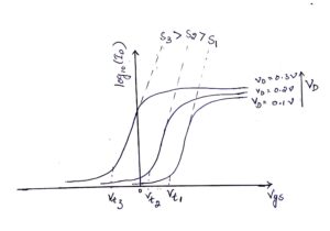
Figure 4: Subthreshold Slope: S3>S2>S1
As drain voltage increases, the Subthreshold slope is increasing; so threshold voltage is getting reduced. And if V t is reduced the leakages current will increase.
How to reduce corner effects?
In FinFET, we have a thin fin surrounded from gate around it. To reduce corner effect in FinFET. we use Hard Mask on top of the fin. Hard Mask has been nothing, just excess gate oxide layer over fin top.
Figure 5: Hard Mask over fin
In multi-gate FET, we just curve the interior corner of the fin so that premature channel should not form. If we increase the radius of curves, corner effects can be removed from the device. And also we get maximum current in the device because the leakage current is reduced. This is one of the reasons why we don’t prefer higher number gate electrodes because we face a lot of corner effects
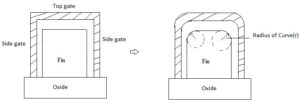
Figure 6: Corner effect removal in fin
Comments are closed.