UART
UART stands for Universal Asynchronous Receiver-Transmitter. It is commonly used in the microcontroller to communicate with the peripheral. An 8-bit serial data coming from the peripheral device is converted into the parallel form using serial to parallel conversion and parallel data coming from the CPU is converted using parallel to serial conversion. UART uses one wire to send the data and another wire to receive the data. It is an asynchronous type of communication which uses 1 start bit and 1 or 2 stop bits.
UART consist of mainly two core components transmitter and receiver. The transmitter consists of a Transmit hold register, Transmit shift register and control logic. Likewise, receiver consists of Receiver hold register, Receiver shift register and control logic. Both the transmitter and receiver should have good handshaking between them as well as speed should be same so baud rate incorporated. The baud rate decides at which speed Tx and Rx will send and receive the data.The transmit hold register holds the data to be transmitted and receive hold register holds the data which has been received. The transmit shift register and receiver shift register shift the bits to the left or right until a byte of data is sent or received. Control logic will decide when to write or read. Baud rate generator generates a speed ranging from 110 bps to 230400. Generally, 9600 or 115200 baud rate is used by the microcontroller.
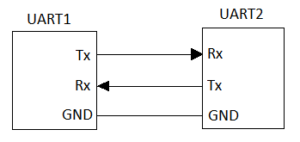
Figure 1: Block Diagram of UART
Working of UART :
UART has two pins for transmission purpose Tx and Rx pin. UART transmits data in the form of packets. The packet contains 1 start bit, 5 to 9 data bits, 1 parity bit and 1 or 2 stop bit. The UART starts the communication with a start bit ‘0′. The start bit initiates the transfer of serial data and stops bit ends the data transaction. To communicate using UART we have to use compatible logic circuits called as MAX232, which converts suitable logic level respective to a device.
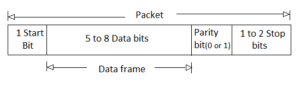
Figure 2: Data Framing in UART
Start Bit: Transmission line is always held at a high level. Whenever a high-to-low transition occurs on transmission line UART will start transferring data at the baud rate.
Data Bit: Data bits can vary from 5 to 8 and if the parity bit is not given it may go up to 9 bits. The data is sent with the least significant bit first.
Parity: Parity bit helps for error checking. Parity can be even or odd. P=0, specifies even parity and it will check for the even number of ones. P=1, specifies odd parity and it will check for odd number ones.
Stop bits: To halt the communication UART holds the transmission line from a low voltage to a high voltage for at least two-bit durations.
Advantages :
- Clock signal is not necessary.
- Error correction allowed by a parity bit.
- Cost effective..
- Provides full duplex communication.
Disadvantages :
- Data frame is limited to a maximum 9 bits.
- Baud rates should be accurately matched for proper communication.
- It doesn’t support multiple slave or master..
ASPI(Serial Peripheral Interface)
SPI is a general-purpose synchronous serial interface. During an SPI transfer, transmit and receive data is simultaneously shifted out and in serially, It is a full duplex communication protocol. A serial clock line synchronizes the data between two serial data lines. SPI devices work on master and slave configuration. SPI protocol uses dedicated lines for data transfer so hardware resources requirement is more. SPI is being used by processors and microcontrollers.
Communication in SPI is done by a master and slave relationship, in which master initiates data frame. When the master generates the clock and selects a slave the data can be transferred either in one or in both the direction simultaneously.
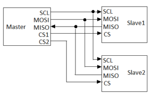
Figure 3: Block Diagram of SPI
SPI uses four dedicated lines:
- Serial clock line (SCL): Clock signal generated by master and use for synchronizing between master and slave.
-
Master Out Slave In (MOSI): Output signal from master and input signal to slave.
-
Master In Slave Out (MISO): Input signal from master and output signal to slave.
-
Chip Select (CS): Output signal from master to select a slave.
Working of SPI:
To start the communication master generates the required frequency on which slave will work and the master pulls the CS line low of the respective slave, which it wants to communicate. Data transfer will take place between the master to slave or slave to master when the clock is given. Whenever the master wants to stop the communication it pulls the CS high and stops generating the clock signal.
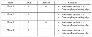
SPI configuration is done by using two parameter:
1)Clock Polarity(CPOL):It decides the which clock format has to be used. There are two clock format permitted non-inverted and inverted.
CPOL=0, specifies non-inverted clock format in which low level of the clock signal is considered as idle state and high level is considered as an active state.
CPOL=1, specifies inverted clock format in which high level of the clock signal is considered as idle state and the low level is considered as an active state.
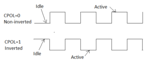
Figure 4: Clock Polarity
2)Clock Phase(CPHASE):It decides on which edge data should be a toggle and on which edge data should be sampled.
CPHASE=0, specifies data will be sampled at the leading edge.
CPHASE=1, specifies data will be sampled at the trailing edge.
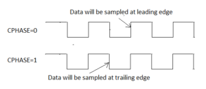
Figure 5: Clock Phase
SPI Modes:
There are four modes of operation in SPI.
SPI is a full duplex communication protocol supports a high data rate of 10MHz (10 Million bits per second). SPI provides very easy hardware implementation.
Advantages :
- Very simple hardware interfacing.
- Provides full duplex communication.
- Data transfer is not limited to 8 bit, a user has complete flexibility.
- It supports multiple slaves.
- It has dedicated lines to transmit and receive.
Disadvantages :
- Hardware overhead because of dedicated lines.
- It requires more pin on IC package..
- No error checking protocol.
- No handshaking signals..
- It supports only one master.
I2C(Inter-Integrated Circuit)
I2C interface is a simple bidirectional interface which uses a single data line to transmit and receive the data. I2C is a serial 2 wire bus designed to communicate between the IC’s using a minimum number of pins. It is half duplex, synchronous serial communication protocol. The data transmission always initiated by the master. Each device on the I2C bus has a specific device address to differentiate between other devices that are on the same I2C bus. The I2C interface consists of a Serial Clock Line(SCL) and Serial Data Address(SDA). Data transfer may be initiated only when the bus is idle. A bus is considered idle if both SDA and SCL lines are high after a STOP condition. I2C supports transfer speed of around 100kHz (original standard, or 400kHz using the most recent standard).
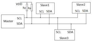
Figure 6: Block Diagram of I2C
Procedure to send and receive the data:
1) When a master wants to send the data:
a) Master sends a START condition and addresses the slave.
b) After getting an ACK from the slave, the master transmits the data.
c) slave sends ACK after receiving the data again.
d) Master terminates the communication by STOP condition.
2) When Master wants to receive data
a) Master sends a START condition and addresses the slave.
b) Master sends the requested register to read to slave..
c) Master receives data from the slave and sends ACK.
d) Master terminates the communication by STOP condition.
START and STOP condition:
In I2C communication master initiate communication by sending a START condition and terminate by sending STOP condition. A high-to-low transition on the SDA line when the SCL line is high defines a START condition. A low-to-high transition on the SDA line when the SCL line is high defines a STOP condition.
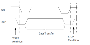 Figure 7: START and STOP Condition
Repeated START Condition :
A repeated START condition is similar to a START condition and is used in place of a back-to-back STOP then START condition. It looks identical to a START condition but differs from a START condition because it happens before a STOP condition (when the bus is not idle). This is useful for when the master wishes to start a new communication but does not want to let the bus go idle.
I2C Data
Data must be sent and received to or from slave as per the master or slave requirement, but this is accomplished by reading or writing to or from slave.
1) Writing to a slave : To write on I2C bus, the master will initiate communication by sending START condition with the address of the slave (7 bit) as well as the 8th bit will be R/W bit, 0 at 8th-bit signifies writing operation. After slave sends the ACK bit, a master will then send the register address where it wants to write. The slave will acknowledge again, letting the master know it is ready. After this, the master will start sending the register data to the slave, after sending the data master will terminate the communication by sending STOP condition.
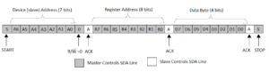
Figure 8: WRITE operation in I2C
2) Reading from a slave : To read from a slave, master instructs slave same as the write operation. To read on I2C bus, the master will initiate communication by sending START condition with the address of the slave (7 bit) as well as the 8th bit will be R/W bit, 1 at 8th-bit signifies reading operation. After slave sends the ACK bit, a master will then send the register address where it wants to read. The slave will acknowledge the read request, and the master releases the SDA bus but will continue supplying the clock to the slave. The master will continue sending out the clock pulses but will release the SDA line, so that the slave can transmit data. At the end of every byte of data, the master will send an ACK to the slave, letting the slave know that it is ready for more data. Once the transmission is done master will send STOP condition to slave to stop the communication.
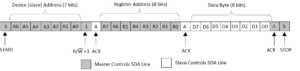
Figure 9: READ operation in I2C
Advantages :
- Required less number of pins as only two lines are needed.
- More efficient in multi-master, multi-slave applications.
- Better error handling with acknowledgement mechanism.
- Cost effective.
Disadvantages :
- It is a half-duplex communication protocol.
- Conflicts may occur in slave while addressing.
Comments are closed.